Let’s Build an affordable Lab Bench Power Supply! My ancient Linear Lab Supply I got as a present from my Dad when I was just a child, still works, but it does not have a current limit and is very inefficient!
Specifications
I will use the DPS5005 Module, as it is cheap, widely available and comes in a lot of power output options. It’s sold on Aliexpress by multiple manufacturers. (Beware of fakes / units that do not deliver the advertised ratings!) The DPS5005 can output a maximum of 50V and 5A, or 250W. It is a switch mode power supply, but for an all-rounder lab power supply I think this will be fine. Since I rarely ever need this magnitude of power, I opted to go for a 150W 36V PSU from Meanwell: the LRS-150-36. The DPS5005 can be programmed to not pull more than the specified supply current available to it. This limits the output current of the unit when at 36V, but with lower output voltages, you can pull higher currents from the DPS.
The LRS line from Meanwell is very special, as the output rail of the power supply is not directly connected to Protective Earth. The output of my power supply is not grounded, meaning I can daisy-chain two of them, to generate a split supply! That’s also the main reason why I’m building two of them, and not just connecting two DPS5005 to the same PSU.
Like my self-made JBC Soldering Station, and so many other projects, the case will be 3D-printed. This time around, I’d like to have a clear acrylic sheet as a cover. It should also be easier to assemble and disassemble.
PWM Fan Controller
I’ve previously built a small PWM Fan Controller with the STM32L031, a SMPS that converts <40V down to 12V, and a temperature sensor. The SMPS is a LT3470A, capable of driving light loads of up to 250mA. That should be enough for a small 40mm cooling fan. The STM32L031 is powered by an LDO, after the SMPS for efficiency, and less self-heating of the PCB. It can use the internal MCU Temperature sensor, or an external NTC, for temperature sensing. I don’t need a fancy smart temperature sensor with I2C just for PWM fan control.
Here is the schematic:
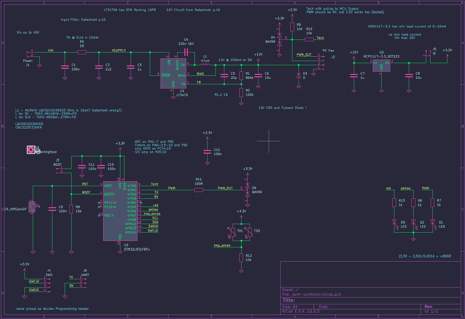
The project can be found here. It includes KiCad design files and the Arduino code. It’s very simple, and does the job just fine! I’ve assembled 3 units of the PCB, two for the power supplies, leaving me with one unit for future projects that need fan control.
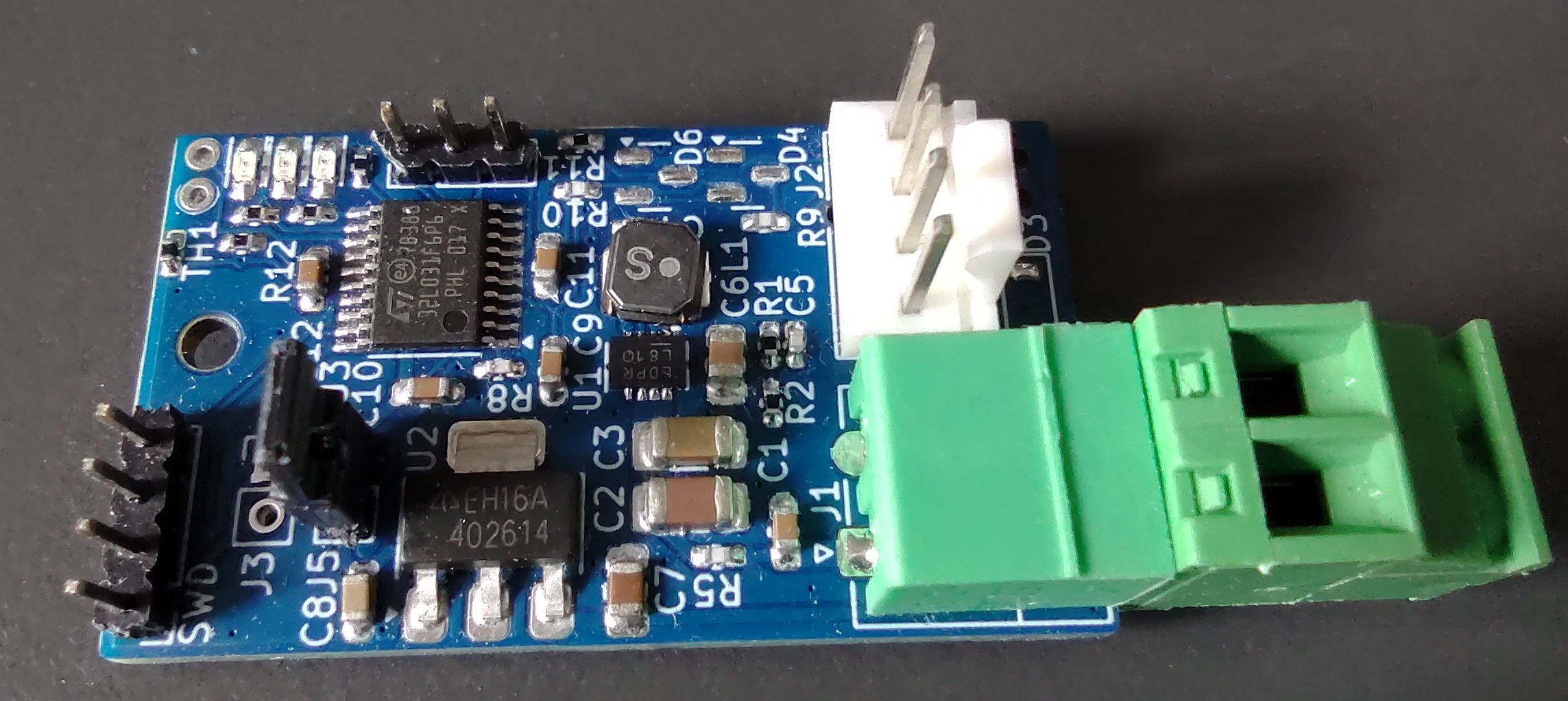
Connections
The mains comes in through an IEC receptacle, and goes through a power switch in to the MeanWell power supply. Protective Earth is connected to the power supply terminal block AND to its metal case! As discussed above, The power supply is connected directly to the DPS5005, providing 36V. The Meanwell PSU powers the fan controller as well. The DPS5005 output goes directly to banana plugs on the front panel. Besides the small serial/UART cable with a USB Isolator for remote control of the DPS5005, that is all the wiring in the power supply.
FreeCAD & 3D-Printing
After a couple small things here and there, this is my first big project I have exclusively designed in FreeCAD. It has gotten incredibly good. Still, expect an unhealthy amount of crashes.
The case I designed is actually quite nice. It features precise cutouts for airflow (speed holes) through the Meanwell PSU, both at the front and back of the unit. I think this makes it look very cool! It features tear-drops instead of normal holes (for the bigger holes at least) and chamfers under over hangs, to improve printability.
I’ve gotten quite good at inserting threaded standoffs. The trick is to insert it almost all the way, just a bit shy of flush with the 3D-Print, and take a flat piece of metal and press it onto the standoff and print. This ensured the standoff is flush, and the 3D-Print will not bulge out.
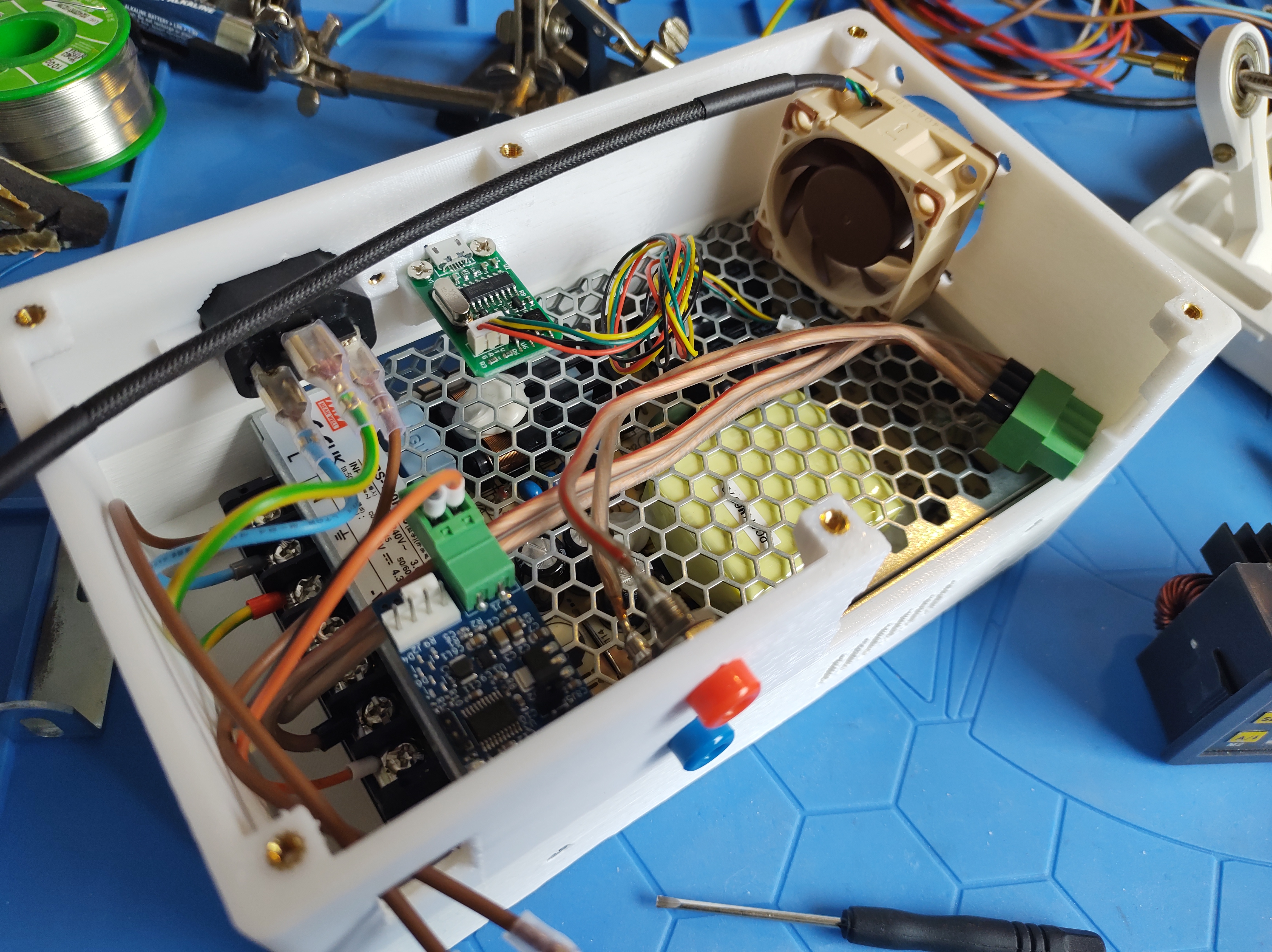
The MeanWell power supply is inserted into the case from the bottom, and held in by 4 screws. One screw from the bottom, and 3 from the front. The fan is mounted like any computer fan would be. The DPS5005 is held in entirely by its plastic clips on either side. It’s a snug fit, and unclipping sadly requires a screwdriver. Everything else, except the fan controller PCB, is held in with M3 screws. The fan controller PCB has a hole for M2.5 screws. My next designs will, unless strictly necessary, never use M2.5 again. M2.5 is fiddly, and over my 15 years of collecting components, including screws from teardowns, I’ve barely collected any of them. For something like this M3 is good, there’s no need to go smaller.
BOM
| Part | No | Price |
|---|---|---|
| DPS5005 Power Supply | 1 | 32 to 50 € |
| MeanWell LRS-150-36 Power Supply | 1 | 17 € |
| 3D-Printed Case, Filament only | 1 | 3 € |
| M3 threaded inserts | 11 | 1.03 € |
| M2.5 threaded inserts | 1 | 0.09 € |
| White Power Switch | 1 | 0.32 € |
| IEC Receptacle | 1 | 0.40 € |
| PWM Fan Controller | 1 | 10 € + assembly time |
| Noctua NF-A4x20 PWM Fan | 1 | 15.90 € |
| or Arctic S4028-6k PWM Fan | 1 | 10 € |
| Banana sockets, different colors | 2 | 3 € |
| Laser Cut Acrylic, with holes | 1 | 8 € |
I’m leaving out crimps and spade connectors, cabling and screws needed for assembly. In total, you are looking at anywhere from 84 to 108 €, depending on your part choice.
Final Thoughts
Here you can see it power my bachelor thesis project: a Class-D audio amplifier.
The power supply is barely breaking a sweat, at 40W peak power of the amplifier.
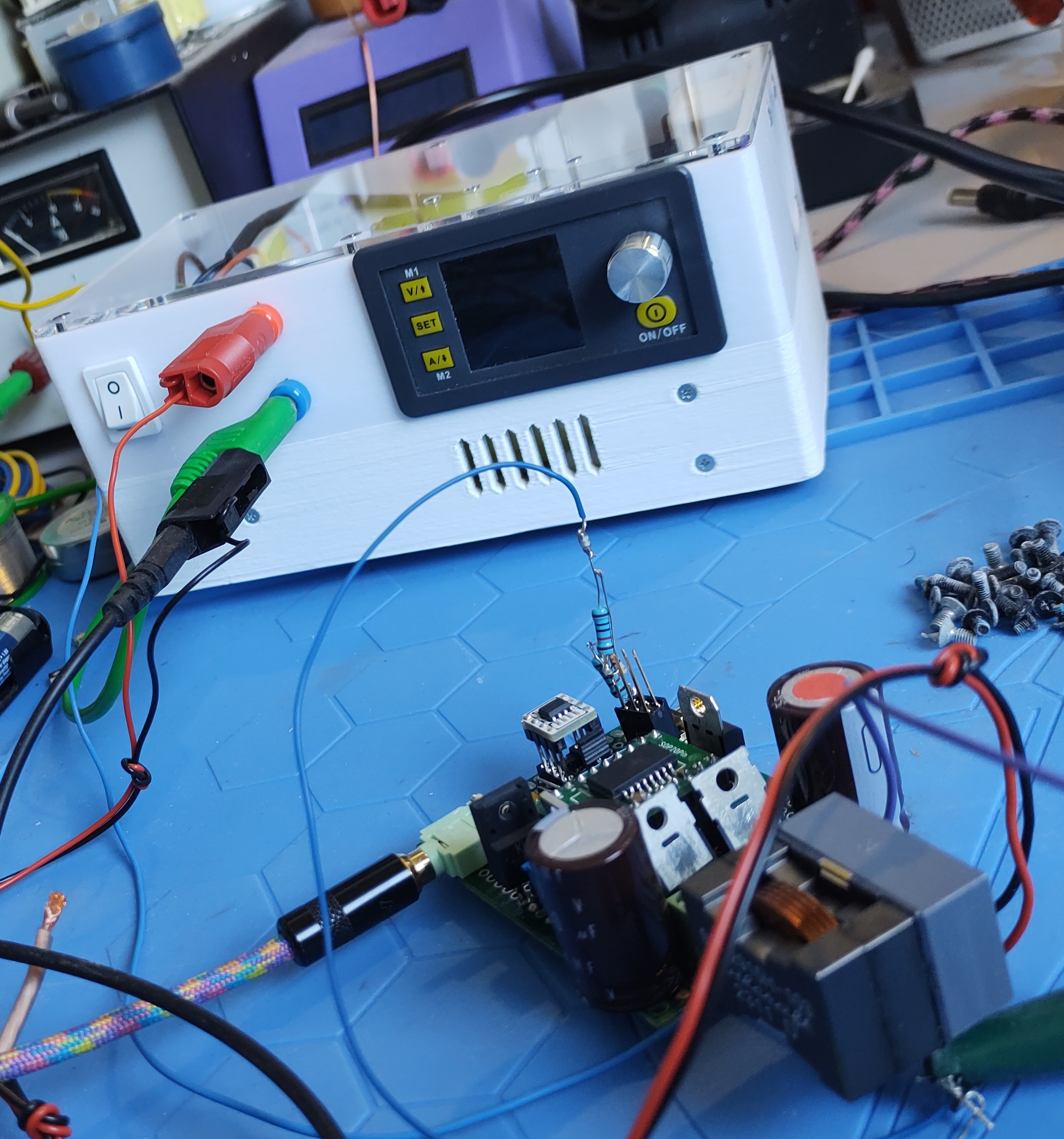 Also, notice how the case looks kind of divided, with a horizontal line going across?
My printer ran out of filament, but I have learned from my past mistakes,
and installed the filament runout sensor some while before printing the case.
Also, notice how the case looks kind of divided, with a horizontal line going across?
My printer ran out of filament, but I have learned from my past mistakes,
and installed the filament runout sensor some while before printing the case.
Oh, and here is unit number two.
I have not bothered giving them serial numbers.
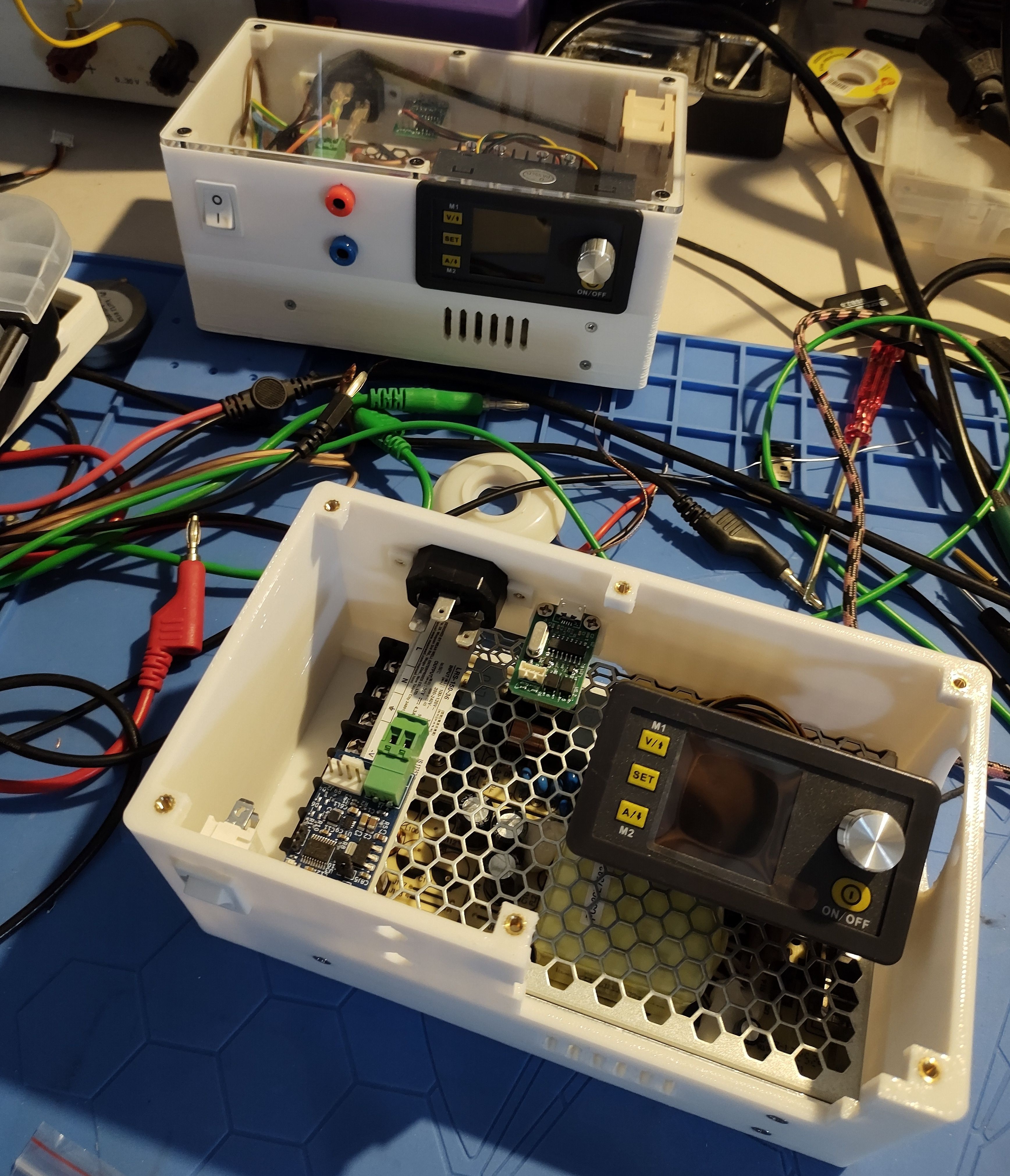
I love the white power switch! Overall, I think the power supply, besides the weird gray tone of the DPS5005, came out nice and professional!
Bonus
During the write-up of this blog post, I found a most intriguing open source development: opendps It re-implements the firmware for the DPS5005, with an ESP32 for wireless connectivity. It even connects